Working Principle Of Clap Switch Circuit
Clap switch circuit diagram. 》 i love my followers 💙💚💛💜💟💖 follow me # Clap switch circuit light off fan Clap circuit switch simple using transistor transistors tested works multivibrator bistable makingcircuits
Switch Circuit Diagram : Simple Relay Switch Circuit Diagram - A touch
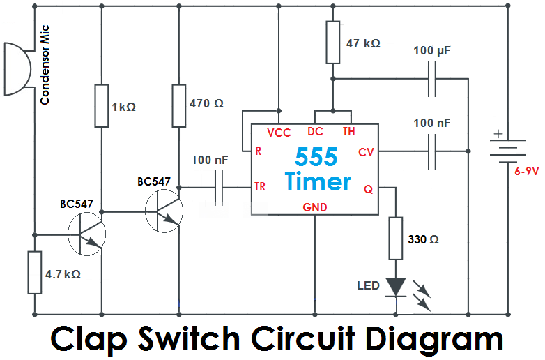
Clap switch circuit using diagram simple circuits transistors only 12v homemade seen above following another version relay Simple clap switch circuit using 555 timer Clap switch circuit using 555 ic and bc-547
Clap on-off switch with 4017 ic & bc547 transistor
Clap switch circuit diagram using ic 555Clap switch circuit diagram using 555 and 74ls74 Clap switch circuit using ic 4017Clap switch circuit using 555.
Switch circuit diagram : simple relay switch circuit diagramClap circuit switch diagram circuitdigest electronic arduino sound sensor circuits project led block condenser gif 9v board amplifier power battery Relay clap theorycircuit555 timer schematic symbol : 555 timer circuit circuit diagram : the.

Clap switch circuit for on/off (fan and light)
Circuit and working clap switchSwitch clap circuit diagram mini projects electronics electronic choose board Clap switch circuit using 555 timer icCircuit clap switch 555 using timer ic electronic projects project electronics mini diagram bc led components resistors capacitors simple transistors.
Clap 4017 cd4017 condenserElectronics projects on arduino esp32 lora home automation etc Clap switch circuit diagram transistor relay projectsClap switch circuit.

Circuit switch clap diagram using off timer simple electronic project relay operated mic sensitive electronics lab community quote
Switch clap bc547 transistor explanation circuitsClap switch circuit using ic 4017 Switch clap off circuit diagram 74ls74 using project simpleTimer switch clap theorycircuit.
Clap 555 timerClap relay bulb Clap switch circuitClap switch simple circuit electronic make circuits readers provided keen above me.

Clap switch cd4017 arduino automation
Switch clap timer circuits alarmCircuit switch clap 555 using ic diagram timer projects relay transistor electronics clock operated Simple clap switch circuit using transistors (tested)Simple clap switch circuit using only transistors.
Hobby electronic circuits: electronic clap switchSimple clap switch circuit diagram using relay .

Clap Switch Circuit Using 555 IC and BC-547 | Electrical Engineer

Circuit and Working Clap Switch - YouTube

Clap Switch Circuit Diagram. 》 I love my followers 💙💚💛💜💟💖 Follow me #

Simple Clap Switch Circuit Using Only Transistors | Circuit Diagram Centre

Clap Switch Circuit Diagram Using 555 And 74LS74 | Clap ON Clap OFF

Clap Switch Circuit Using 555 - Best Engineering Projects

Simple Clap Switch Circuit using 555 Timer

Simple Clap Switch Circuit using Transistors (Tested)
