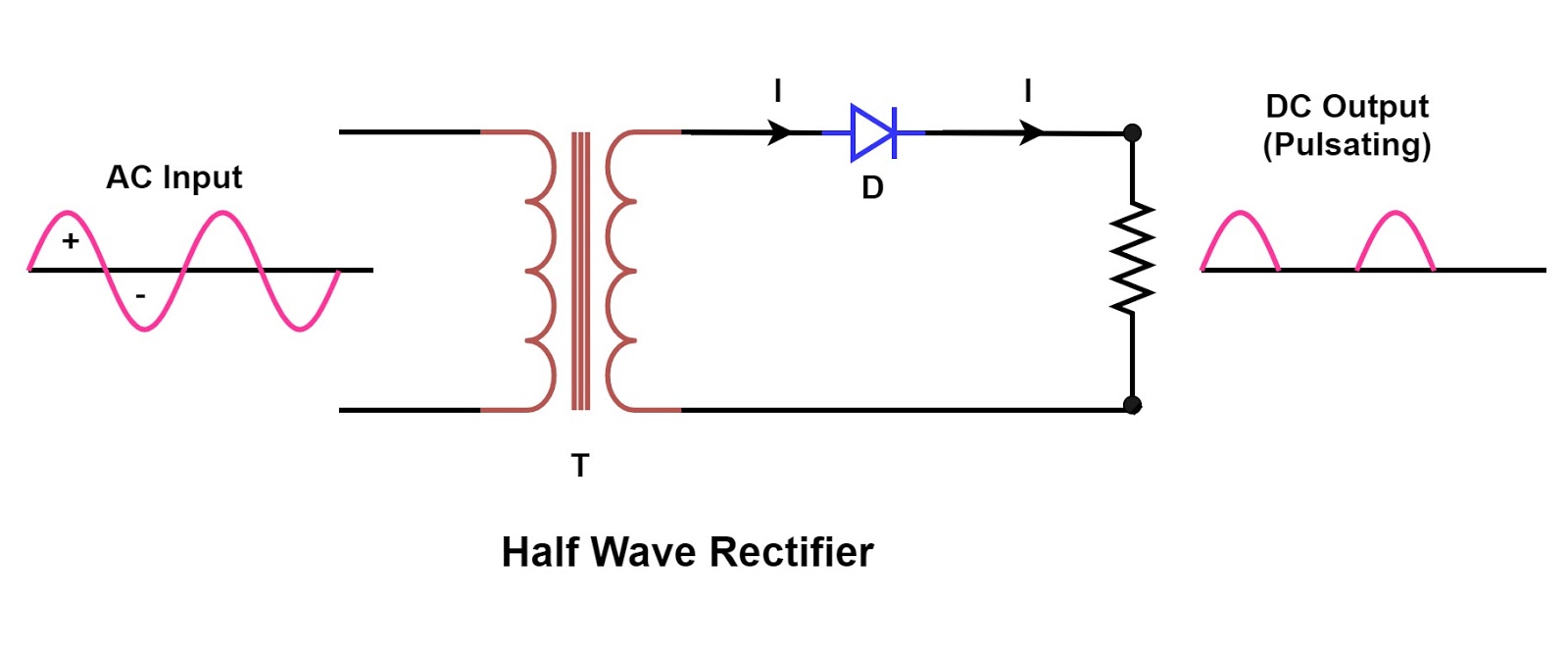
Suitable Circuit Diagram
(a) with the help of a suitable circuit diagram prove that the Circuit dsb sc carrier modulation input why biasing sure dc both used not Single phase half wave rectifier- circuit diagram,theory & applications
Schematic structure of the full-wave rectifier under study. | Download
Rtd working principle Simple radio receiver circuits for beginners Ht circuit supply power receiver mains diagram valve low safe suitable powering
Ic voltage regulators-with circuit diagram
(a) with the help of a suitable circuit diagram prove that theSchematic structure of the full-wave rectifier under study. Voltage ic diagram regulator block circuit terminal fixed regulatorsWorking principle temperature resistance detector rtd used rtds platinum material construction electrical metals coefficient positive having.
.


Simple Radio Receiver Circuits For Beginners

RTD Working Principle - your electrical guide

IC Voltage Regulators-with Circuit Diagram - Design & Theory

communication - DSB-SC modulation circuit - Electrical Engineering

(a) With the help of a suitable circuit diagram prove that the

Schematic structure of the full-wave rectifier under study. | Download

(a) With the help of a suitable circuit diagram prove that the
