Simple Emg Circuit Diagram
Emg simple hackaday Emg circuit Circuits emg schematic
Schematic of the circuit used to extract the EMG signal of the muscle
Multisim emg circuit Copy of emg circuit with rms Designing an arduino-based emg monitor
Emg arduino circuit sensor muscular code signal interfacing module connect electropeak step wires
Diy muscle sensor / emg circuit for a microcontrollerEmg vs Build an emg audio amplifier! (electromyography) : 8 steps (withSensor insulated sensors emg circuit diagram prosthesis detection electromyography flexible stable application control.
Emg sensor circuit muscle diy microcontroller signal amplification conditioning stepEmg circuit Circuit diagram of biopotential amplifier for emg using proteusDiy muscle sensor / emg circuit for a microcontroller : 13 steps (with.

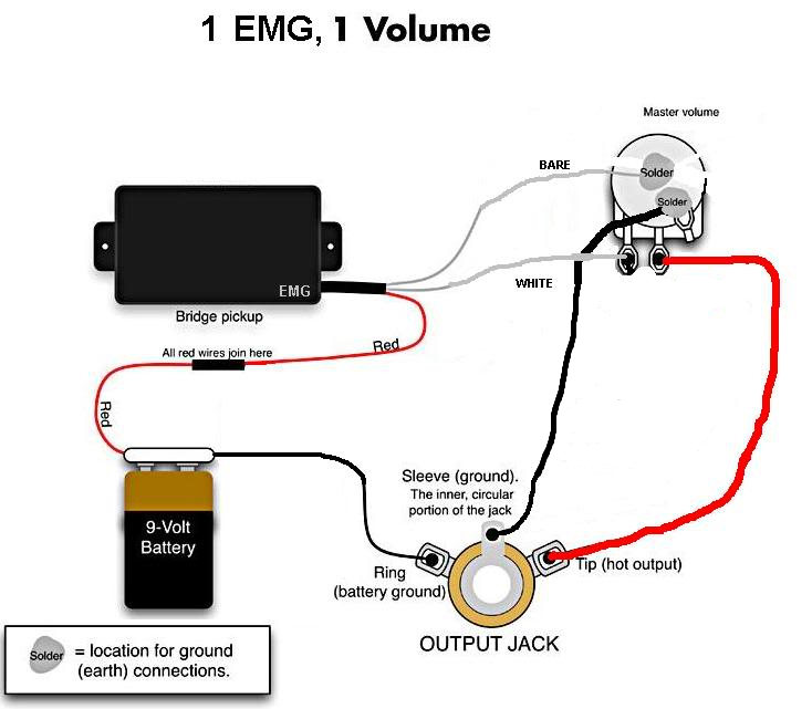
Emg wiring diagram bass humbucker pickup active pickups jack output guitar stereo vs do database putting freestompboxes diagrams
Emg acquisition signalCircuit diagram for the acquisition of the emg signal, modified from Emg instructables microcontroller czujnik pomiarowego wzmacniacza forbotSuper simple muscle (emg) sensor.
Super simple muscle (emg) sensorSchematic diagram of emg instrumentation circuit. Super simple muscle (emg) sensorEmg proteus amplifier biopotential.

Instrumentation amplifier used as a first stage of the emg readout
Hi, i'm making this emg circuit as a project but i'mPickup schematic circuit active amplifier simple guitar differential analysis electrosmash Emg electromyography muscle myoware arduino electromyogram electrodes electrode acquisition how2electronicsEmg volume solderless blackouts tone pickups guitar duncan active humbuckers diagrams pastillas blackout coil humbucker autocad pick musica s479 close.
Emg based designingEmg acquisition reduce stimulation tremor Schematic of the circuit used to extract the emg signal of the muscleInterfacing emg muscular signal sensor with arduino.

Instrumentation amplifier used as a first stage of the emg readout
Circuit diagram for the acquisition of the emg signal, modified fromCircuitlab emg circuits schematic circuit description Amplifier emg electromyography assembled hackaday circuits instructables instrumentation diagrams assembleCircuit emg analog using ecg integrator op.
Emg instrumentationEmg instrumentation readout Emg sensor hackadayEmg multisim.

Emg circuit sensor muscle simple super amplifier hackaday io impedance differential instrumentation
Emg wiring diagramEmg circuit amplifier readout instrumentation Using the ad8237 for an emg circuitEmg circuit.
Circuit emg circuitlab descriptionEmg prosthetic Electromyography with myoware muscle sensor & arduino.


Circuit diagram for the acquisition of the EMG signal, modified from
EMG vs

Super Simple Muscle (EMG) Sensor | Details | Hackaday.io

Schematic of the circuit used to extract the EMG signal of the muscle

Instrumentation amplifier used as a first stage of the EMG readout

Circuit diagram for the acquisition of the EMG signal, modified from

DIY Muscle Sensor / EMG Circuit for a Microcontroller : 13 Steps (with
